If your Classic Aurora has 20% or darker window tint, have a back-up camera(w/o night vision) or have to back up in pitch dark for a length of time then this is for you.
Factory bulb is a 3155. It puts out 264 lumens and operates at 20.48W!!! The XM-L LED puts out 1000 lumens and operates at 100 Lumens per Watt!! So, more than twice as bright and efficient!!
Materials & Parts:

- 2x - OEM Reverse Lamps Bulb Socket(Salvage Yard)
- 2x - Star LED Heatsink
- 2x - XM-L T6 LED
- 2x - 3A Constant Current Driver
- 2x - 1k(1000 Ohms) Resistor(Radio Shack for small quantity)
- 2x - Virtual Filament
- 4x - 4-40x0.5” Button Head Screw (Lowes, Home Depot, Any Hardware Store)
- 2x - 4-40x0.25" Button Head Screw (Lowes, Home Depot, Any Hardware Store)
- Heat Shrink Tubing (Lowes, Home Depot, Any Hardware Store)
- Heat Sink Compound(Not going to make a suggestion here because some are picky about heat sink compound)
- ~12 of 22 AWG wire Black and Red(Lowes, Home Depot, Any Hardware Store)
Step One: Remove Insert From Reverse Lamp Bulb Socket
Pry Tabs Toward Center of Bulb Socket:


Pull Up with Pliers to Remove Insert. You will have to dremel some plastic out of the bottom of the socket. I didn't get a picture of that.

Step Two: Configuring the LED Driver:
This driver is made to have three modes. High, Low and strobe. We only want high so we need to modify the driver a bit.
Trace the center lead back to it's solder joint on the main board:
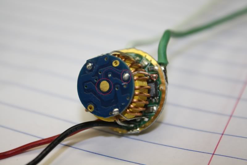
Then locate the solder joint next to IC1:
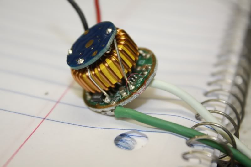
Cut off the daughter-board and solder a 1k resistor between the 2 points:
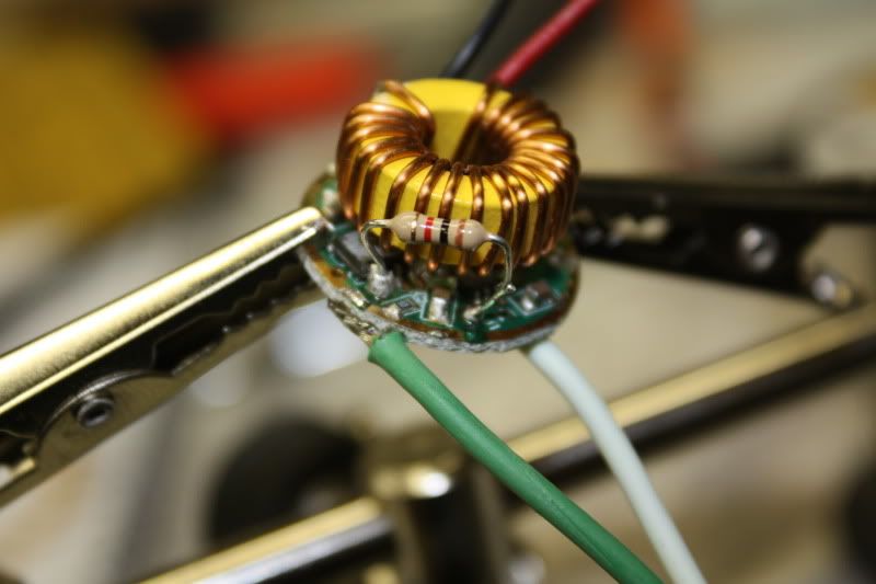
Add some heatshrink tubing over resistor. This is so later the heatsink or inductor wont short out the drive and tuck against the inductor.

Step Three: Wiring the LED Driver
Cut 6" of wire. Strip and tin the End of the Wire Leads:

Solder the tinned wires to the LED Driver. Inside ring is Positive(+). Outside Ring is Negative(-) These leads go the power source!

With the other 6" of wire strip and tin both ends and strip and tin the black and red wires on the LED driver. Solder the 6" tinned wires to the respective wires on the LED driver.

... and heatshrink.

Step Four: Assembling the Final Product:
Place Power Input Wires(bottom of board) through reverse lamp bulb socket and place place driver inside bulb socket. Tuck positive and negative LED output wires to opposite sides.

Insert Heatsink into bulb socket aligning the LED output wires. Press into place. Then trim, strip and tin the output leads to the LED.

Add some heatsink compound to heatsink.

Place LED on heatsink with 1/4" screws and solder wires in place. Make certain to observe polarity!

Test fire! Make sure to observe polarity!! The driver can operate from 6-18V DC.

Remove screws holding the LED. It will stay in place now that it is soldered. Place virtual filament over LED and screw into place with 1/2" screw. If you are curious to the virtual filament it basically takes forward emitting LED and emits the light out and 360* so we can still utilize the reflector throw the light in necessary locations as factory did. Only More intense with more throw.
[center]
 [/center]
 [center]Aw, why not test fire!

[/center]
Then you can either hard wire it in, use a waterproof 2 way connector or solder a bulb base to PnP with existing factory bulb socket.


[center]
Here are some pictures of the bulb in the reverse housing.

 [/center]
 Took these comparisons last night:
Output shot on the garage door. LED bulb on left side of picture and filament on right side. It almost looks like filament is not on haha! :P


Some output shots other than color temp and brightness comparison. Here you can see the throw of the LED
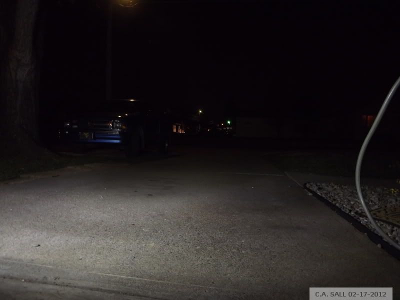
Both pictures taken in same location with identical camera settings seconds apart.


